
by Frank Giffen
Yeah, most people use pedalboards, but I just had to be different. I was under pressure to reduce my on-stage footprint. First they thought I should use fewer pedals, but that, of course, is crazy talk. So what’s a player to do? Relocate, was my thought. Need the pedals, no question about that, but do they really need to all be on the floor in front of me? It’s nice to have that as a dashboard for what’s going on while playing, but I don’t change settings on most of them over the course of a show, I don’t feel the need to re-sequence them in mid-song or mid-show, I just turn them on and off as needed. I could get a Boss ES-8 and repurpose my Roland FC-300 to control it via MIDI, but that would be about $600 just for the ES-8, and might be a little more complex than I need, not to mention costly.
So I thought I had once seen someone who put all their pedals in a multi-drawer toolbox, though I don’t recall how they controlled them, nor could I find any pictures online from which to draw inspiration. So the thinking process commenced. Am I doing something innovative and unprecedented, or is this just a bad idea and that’s why nobody’s done it before? I opted to find out. Along the way, I learned of another pedalboard option and was offered a beta test of it, but then that didn’t work out, so I took it for a sign that this was the way to go.
Obviously (well, it should be obvious), you can’t buy one of those passive loopers and run a pair of 14-foot cables for each pedal to and from it. That wouldn’t sound too good (or at all) and would create a cabling mess. But what if, there was a looper that could be controlled remotely, maybe wirelessly, that could turn pedals on and off using small footswitches like Boss FS-7s? And what if it sat in an easily transportable container could store the pedals safely when not in use and where their settings wouldn’t be subject to bumping or other maladjustment while in use, but could still be easily accessed? And that container could be easily loaded in and out, connected and disconnected? And what if it could control an amplifier, too, and replace the amp’s footswitch? Yeah, that’d be perfect. Except it didn’t exist. Yet.
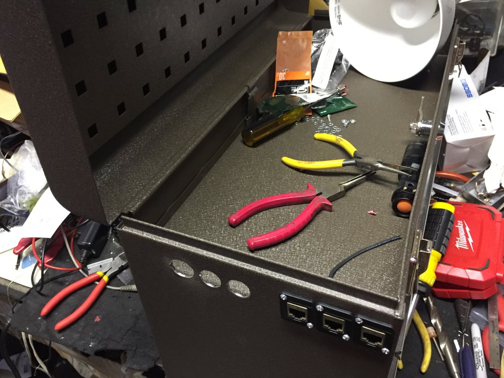
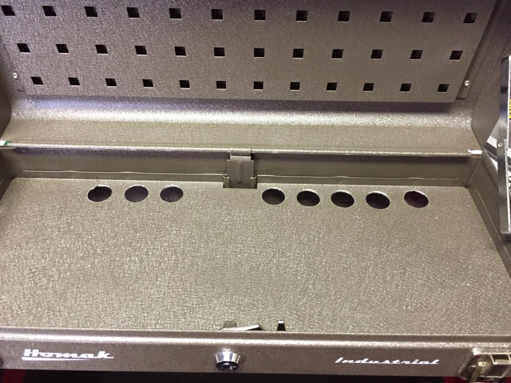
OK, I haven’t figured out the wireless capability yet (though IK Multimedia has come out with a programmable wireless MIDI foot controller, but that’s not quite what I had in mind), but I think I got the rest of it handled. And I call it the PedalBox. It starts with a Homak 3-drawer toolbox (shown above). I chose this particular model because the drawers are deep enough to hold most pedals, and it’s pretty good quality so it ought to stand up to road use, and it locks with a real “Ace” type lock so the pedals won’t disappear too easily. A modestly unpleasant surprise occurred when Amazon delivered the toolbox. That sucker is heavier than I thought it would be, and that’s without anything in it. I rationalized this to believe that will make it harder to steal.

The Strymon pedals have to sit in the top or bottom compartment because they’re the tallest I have. Probably the bottom compartment because I’ll need space in the top compartment for the control box, the wireless receiver, and the tuner. The control box, which I had to build, sits in the top so the LEDs that indicate what loop is on and what loop isn’t can be seen (for maximum coolness).
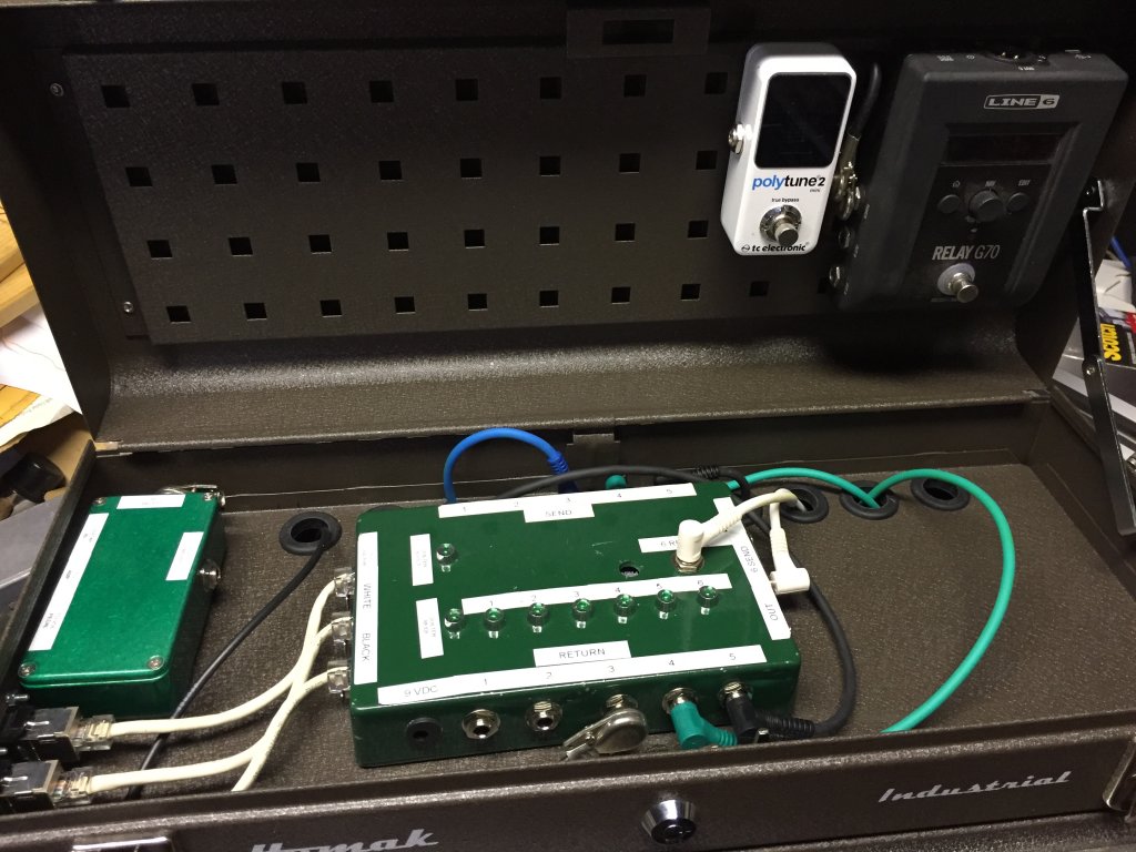
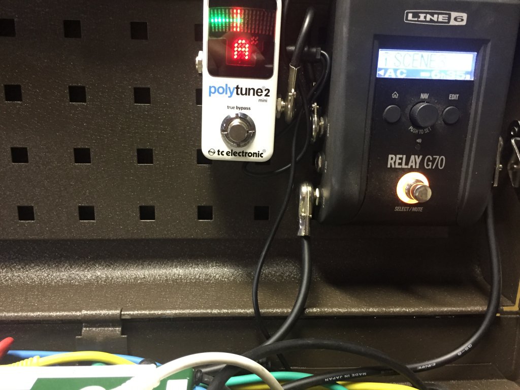
The Line 6 Wireless base is mounted upside down in the lid so when the lid flips up, it’s able to optimally receive the transmissions from the transmitter. The tuner will sit next to the Line 6 so it can be easily seen, and because it plugs right into the Line 6 anyway.
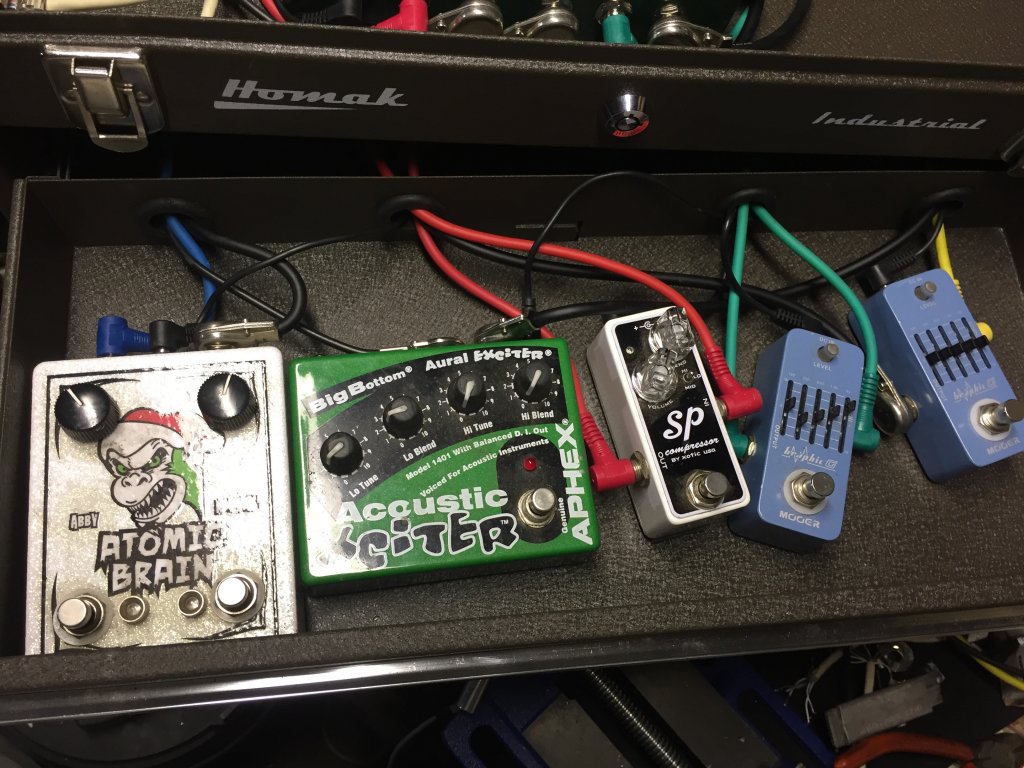
The Voodoo Labs Mondo power supply (yes, that’s really its name) is in one drawer,
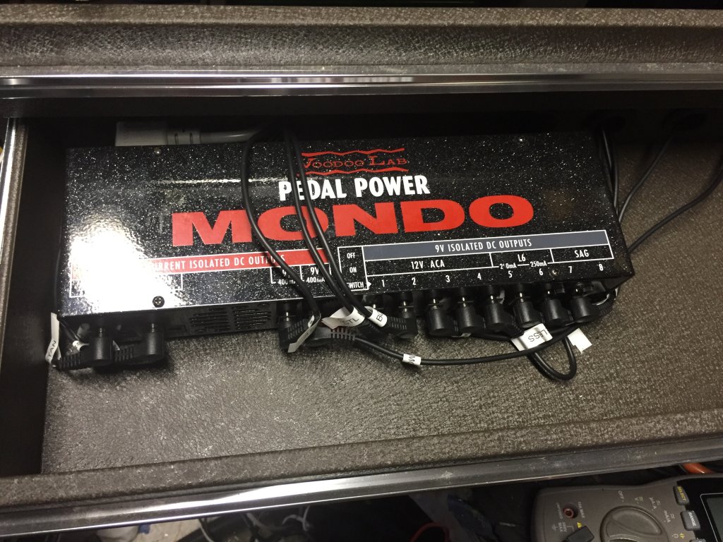
and the rest of the pedals are in other drawers.
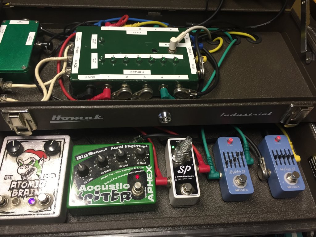
The power and audio cables go through notches or holes I had to cut in the backs of the drawers to accommodate them.

I had to cut a hole in the back of the toolbox for an IEC inlet to power the Mondo,


and drill some holes for a few ¼” jacks (one for an optional wired input, one for the output to the amp, one for a TRS loop to a volume pedal), and 3 CAT6 jacks.
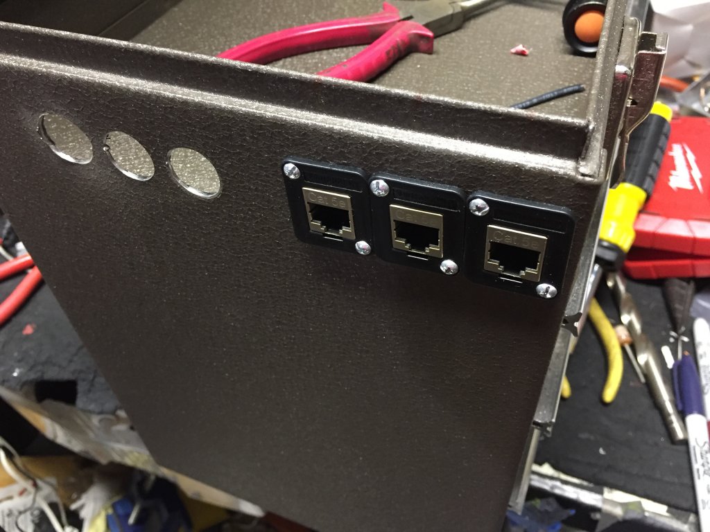

Two of the CAT6 jacks go to the footswitch board with the FS-7s on it (one provides power to the FS-7s and switches the pedals in and out, one is dedicated to the amp-footswitch eliminator, and has 5 extra conductors for future inspirations), the third CAT6 goes to the amp to drive its footswitchable functionality.
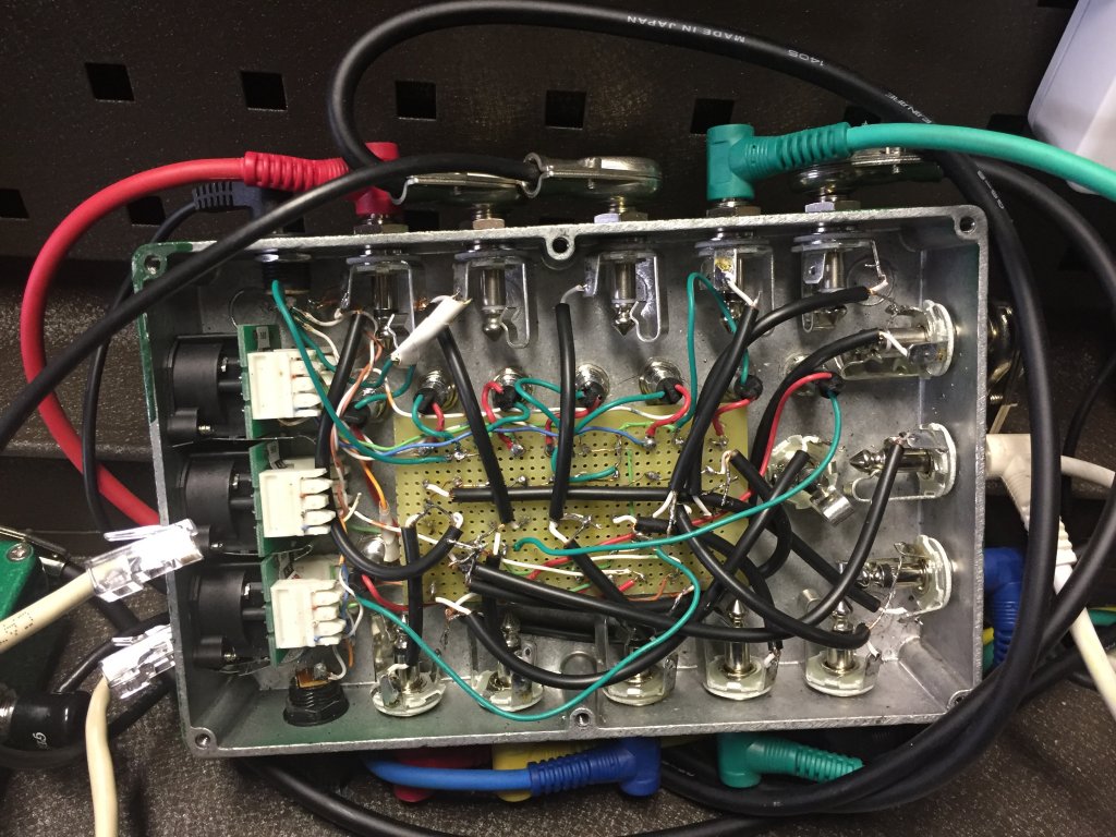
So how does it work, you ask? The secret, if there is one, is audio relays. By energizing the electromagnetic coil of the relay, a switch can do any of a couple of things: it can go from off to on, on to off, or from on to on on another circuit, or off to off on another circuit. For a loop switcher, the signal for the send and the return need to be sent to different places, depending upon whether it’s on or off (in our out of the loop). And when the pedal is not in use, its return has to be disconnected from the signal chain so it doesn’t adversely affect the tone. So by using a DPDT relay, two things are switched when the coil is energized (a.k.a., turned on), and they’re switched back when the coil is turned off.
And that’s how the Pedalbox works. The FS-7 footswitches take a +9V DC current and send it to the coil of their assigned relay. When the current hits the relay, it energizes the coil, turns on the LED (again, maximizing coolness, and nothing does that like LEDs), and the energized coil pulls the switch in, thereby re-routing the audio signal out to the effect that’s plugged into it. The other pole on the relay re-routes the returning signal to the output of the loop into the signal chain, and the signal goes on. If it’s one of the first loops, then it goes to the next loop. If it’s the end of the line (loop 6), then the signal goes to the output of the box, which goes to the amp input (well, after going through the shorting TRS jack which may or may have a Boss FV30 plugged into it). So once the input goes through, or skips, all 6 loops, it goes to the output. Shown here is a copy of my first draft of the schematic for the control box I its early stages.
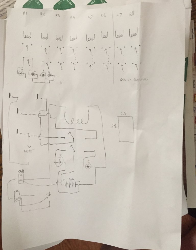
(it got a lot more complex after this)
But wait, there’s more! Besides switching effects in and out of the signal path, one of the Pedalbox’s FS-7s has the ability to turn up to two (for now; I could add more if I really want to) footswitchable options on and off on Quilter amps. I use it to switch the Mode command to switch channels, and to turn the Boost on and off. I have a few spare lines in the second CAT6 cable to do more, if I ever feel like it.
Where to start? I had a number of points of uncertainty in this project, not the least of which was whether the audio relays would work, and how they would sound. So I did a little research to find what make and model relays work the best for an application somewhat like this (since I couldn’t find any record of anyone’s having done it before). Panasonic made some highly-regarded audio relays, as did Omron. Then I remembered the coils had to be 9VDC since that’s what the power supply was providing (yes, I forgot for a moment that the Mondo has a couple of 12VDC ports that I wasn’t even using, so I could have done that, but, too late now). That cut down the number of options, but there was still an adequate selection. So I ordered some on ebay, and set about building a prototype circuit. I took an old Hammond box I wasn’t using, drilled a couple more holes in it to mount some more jacks a power connector, and I opted to let the LED hang out the edge.

I’ve been told in the past that if the circuit sits inside a metal box, using shielded cable inside the box isn’t necessary, but when I first breadboarded it up with long individual strands of CAT5 copper, it hummed like a mofo, and that just wasn’t going to work. So I replaced those with pieces of the Mogami cable I usually use to make patch cables out of, no longer than they needed to be, carefully shielded and all shields grounded. Success! Crazy? Yes, but this just…might…work!!!
So then came the next part, sourcing all the hardware and components. In the course of my travels, I ran across a pedal parts supplier with the best name ever, “Bitches Love My Switches,” at www.bitcheslovemyswitches.com. There I found LEDs with the resistors already installed, Neutrik ¼” jacks, both mono and stereo, and the big Hammond-type box that everything will get shoehorned into. Amazon was instrumental in finding cool things like flat 25-ft. CAT6 cables that take up practically no space, panel-mount RJ45 pass-thru jacks for the side of the toolbox, actual punchdown RJ45 jacks for the control box, drill bits to drill the holes for those jacks, and so much more. But once sourced, to the drill press!
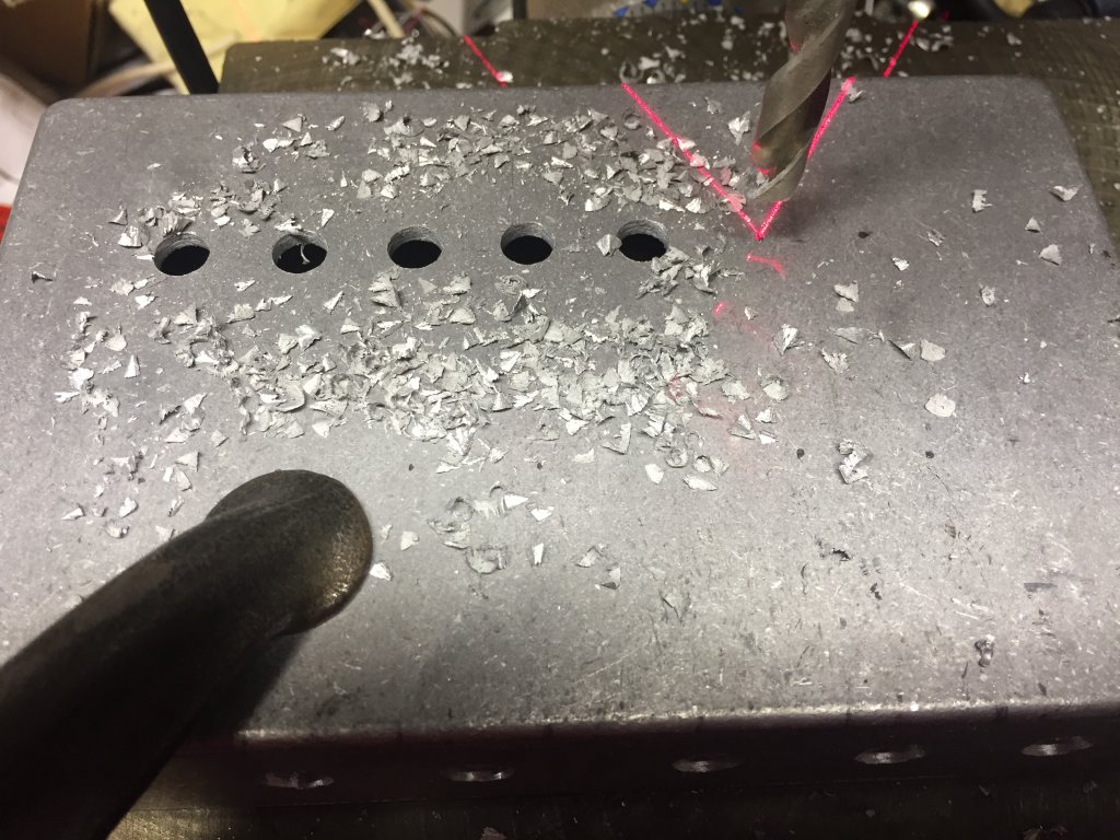
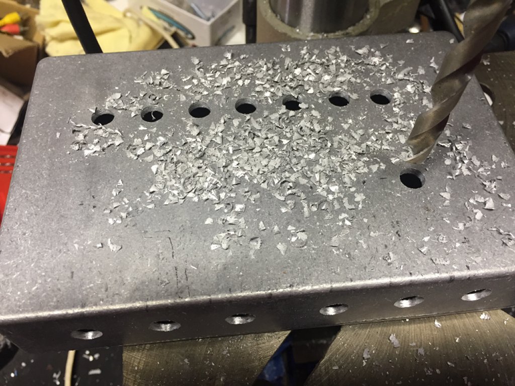
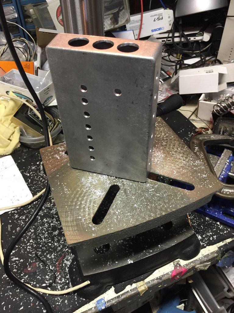
I spent the last half of the Super Bowl and the brief overtime putting 23 holes in the box, and I’m still waiting for the drill bits to arrive to make the remaining 3 holes. Once that’s done, then it’s time to (attempt) assembly. I’ve always marveled at those, which include my dad, his ham radio friends, and the occasional electronics teacher, who said things like “I could fit that into a box this big” (usually while approximating the size with two fingers on one hand). Well somehow, I need to get 8 relays, 9 LEDs, 14 ¼” jacks, 1 power jack, and 3 CAT6 jacks into this box, and a fair bit of wire, too. This is another challenge for this project. Maybe I should have etched a PC board…no! I haven’t done that since high school, and I’m not sure I want to do that again for this project.
My timing could have been a little better, but I just had to go cheap on shipping. The punchdown CAT6 jacks are going to be one of the last things to arrive, and not having them to gauge how big to make the holes for them (the drill bits arrived already) kind of puts assembly of the control box on hold. So until then, I’ll be further testing the circuit, to answer questions like “Will the FS-7s actually work with the relays?” Will there be too much voltage drop across that skinny 25-foot cable?” “Will the little cables provide enough power to run the FS-7s?” Gonna have to try it all and find out.
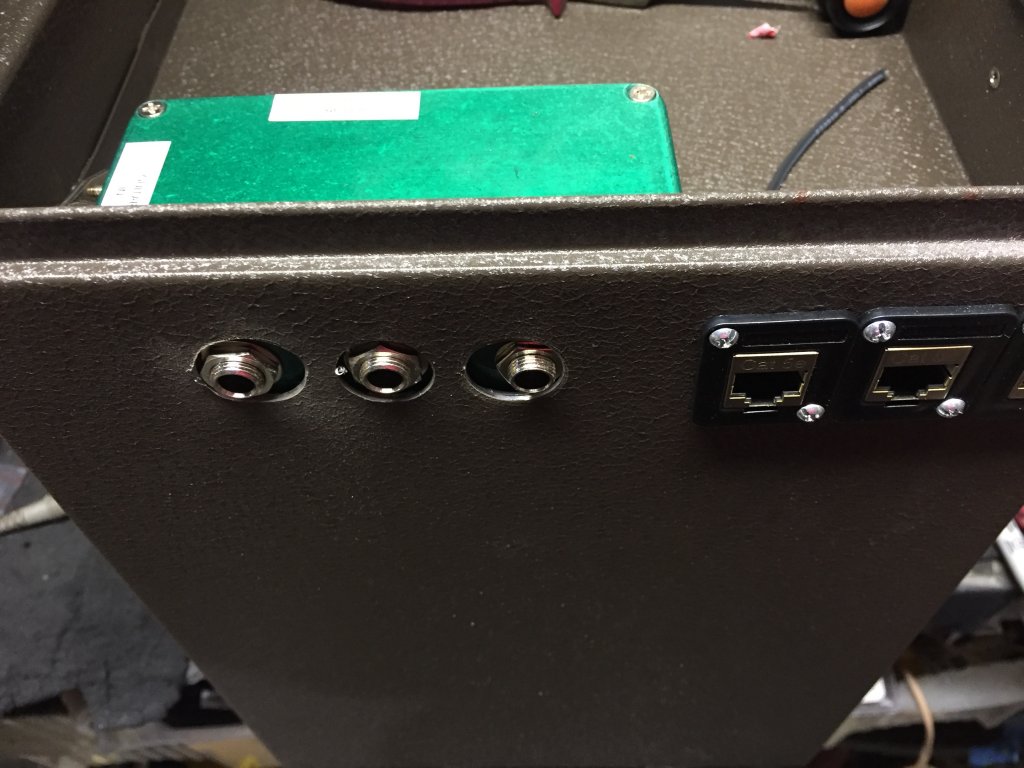
My worries were a bit unnecessary. The punchdown CAT6 jacks arrived the next day, and with a little drilling, they fit into the box just right.

Unfortunately, they blocked 2 of the ¼” jacks from mounting in their intended locations, so there are now two “ventilation” holes in the box and two previously unplanned jacks on the top. It was a rainy day, but I painted the box anyway once I had all the holes in it (some sprinkles gave the paint job a little more texture than I’d planned, but it did get painted),

and after doing that, realized I hadn’t drilled the countersinks in the box for the mounting screws for the CAT6 jacks. Whilst waiting for the paint to dry, I opted to test the functionality of the FS-7 switches with the relays and LEDs, over a long CAT6 cable. Happily, it all worked. Haven’t been able to test the ability of the box to power the FS-7, especially 4 of them, but until I get all 4 of them, I won’t be able to.
And so commenced the assembly. First, mount all the hardware. That took a little while, as all the jacks needed to be installed, and some rotated so as not to bump into each other and short.

Assembly and wiring were a bit tedious, especially the wiring. I initially planned to use shielded cable to minimize the potential for added noise, but recalled that no one else uses shielded cable inside their aluminum box stomp pedals, so I opted not to. And I just stuck the relays to the top of the box with Dual Lock. This looked like hell and was a mess to wire.

Then when I got it done and plugged it in, yikes, was there ever a hum problem. OK, time to go with shielded cables. And while I’m at it, a neater way to wire it, with shorter leads. Not sure why I didn’t do this before, but how about perf board to mount the relays on, and provide a neater, simpler means of connecting? Duh. And I was going to need some thinner shielded cable. And I wanted it now. So off to Fry’s Electronics I went, where I found affordable perf board, but no bulk shielded cable small enough to meet my needs. I did, however, find inexpensive RCA patch cables with thin shielded cable, so I bought two 6-footers and cannibalized them (I ended up only needing one). With the perf board, I was able to use much shorter leads, except to and from the loop jacks, but was able to shield all of them. At first I was planning to mount the board using Dual Lock for standoffs and putting the relays right-side up for neatest appearance. Then I decided that doing so would make the wiring a nightmare, so instead I stuck the Dual Lock on a couple of the relays and mounted the perf board with the contacts facing up, thereby facilitating soldering all the leads on. When I finally got it all done, A) it worked, and B) nowhere near as much noise. Still a little, but tough to notice. In my first iteration of wiring, I figured I’d probably damaged a few of the relays by overheating with all the soldering, desoldering, and resoldering I’d done to them (yes, I know I could have avoided all this by using IC sockets, but that didn’t occur to me until I was well into the project), so I ordered some more (the good news: they’re only $1.50 apiece, the bad news, they have to come from China, which takes a while). But I got tired of waiting and re-used the original ones, and they’re fine.
And of course, the day I finished rewiring with the perf board and the old relays, the new relays arrived. Guess I’m all set for building another one of these contraptions. Which I’ll probably never do.
Now that the relay control box is complete, it’s time to prepare the rest of the project for assembly. Keep in mind that the proof-of-concept on this project is running only a couple of days ahead of actual execution, and I’m trying not to horribly disfigure anything so it can’t be returned or repurposed if we encounter unrecoverable failure along the way.
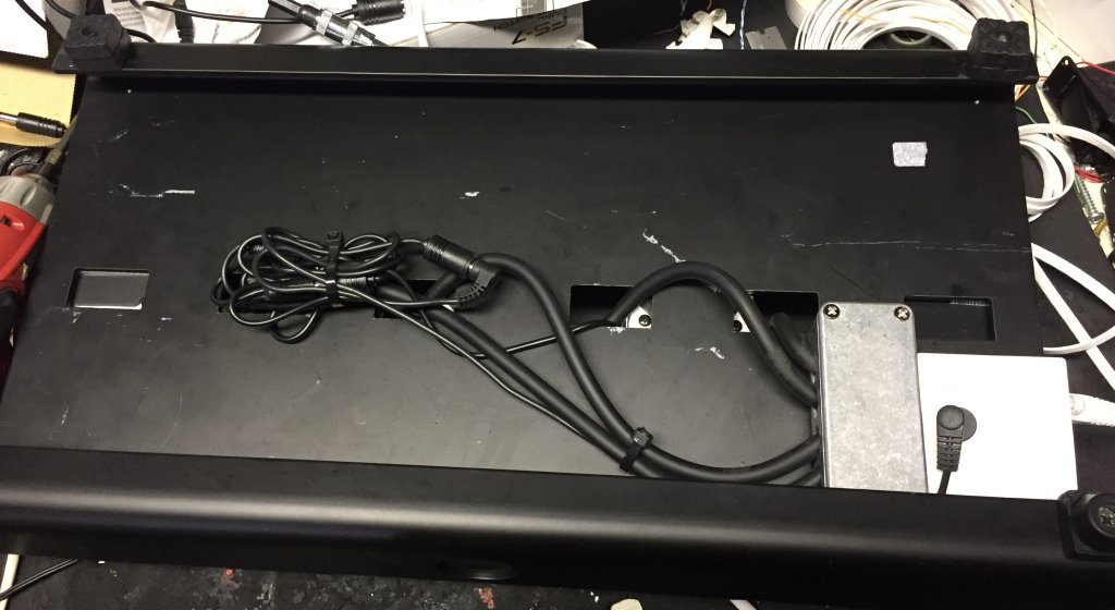
The next step is the foot controller. This consists of 4 Boss FS-7s and a Boss FV-30 mini volume pedal. They’re mounted on an On Stage pedalboard, a one-piece aluminum board that comes with a gig bag big enough to hold the board, the pedals, and the cables.
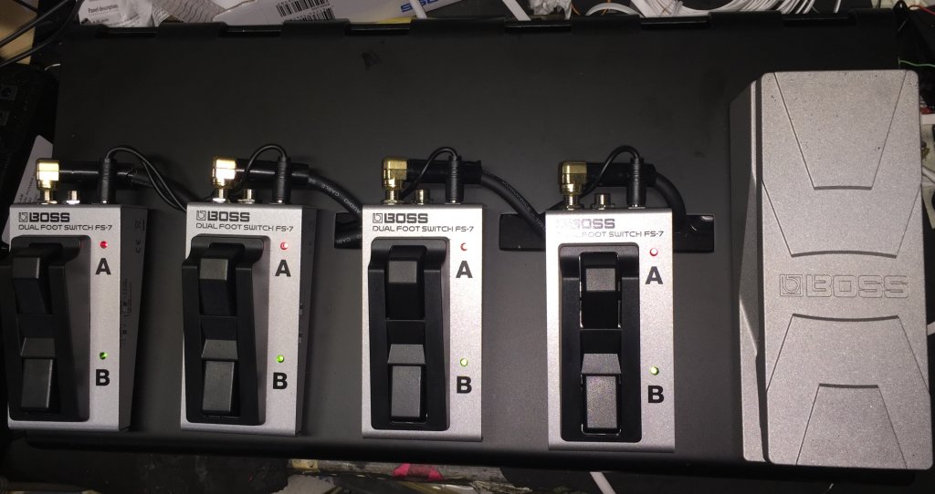
The CAT6 cables connect between the PedalBox and the foot controller via a surface-mount dual CAT5e jack (since I’m just passing DC current on the cable lines, I’m not too concerned as to which category my jacks and wiring are) underneath the board. The FS-7s use ¼” TRS cables, and while I could have used CAT5 or 6 cable into some right-angle TRS plugs, 3 strands of CAT6 cable aren’t terribly rugged, and I was concerned about breakage, so I bought some TRS audio cables and cut them to fit. But as I found out when I tried to wire them, the leads on the TRS cables are 16AWG, which is a little too big to punch into the punch-down block on the jack. And I also had to mount a 9 VDC power jack to power the LEDs in the FS-7s, so in the words of Johnny Cash in “One Piece At A Time,” I’ll need the help of an “A-dapter kit.”
In my case, the A-dapter kit is a small Hammond box with 5 holes drilled in it:
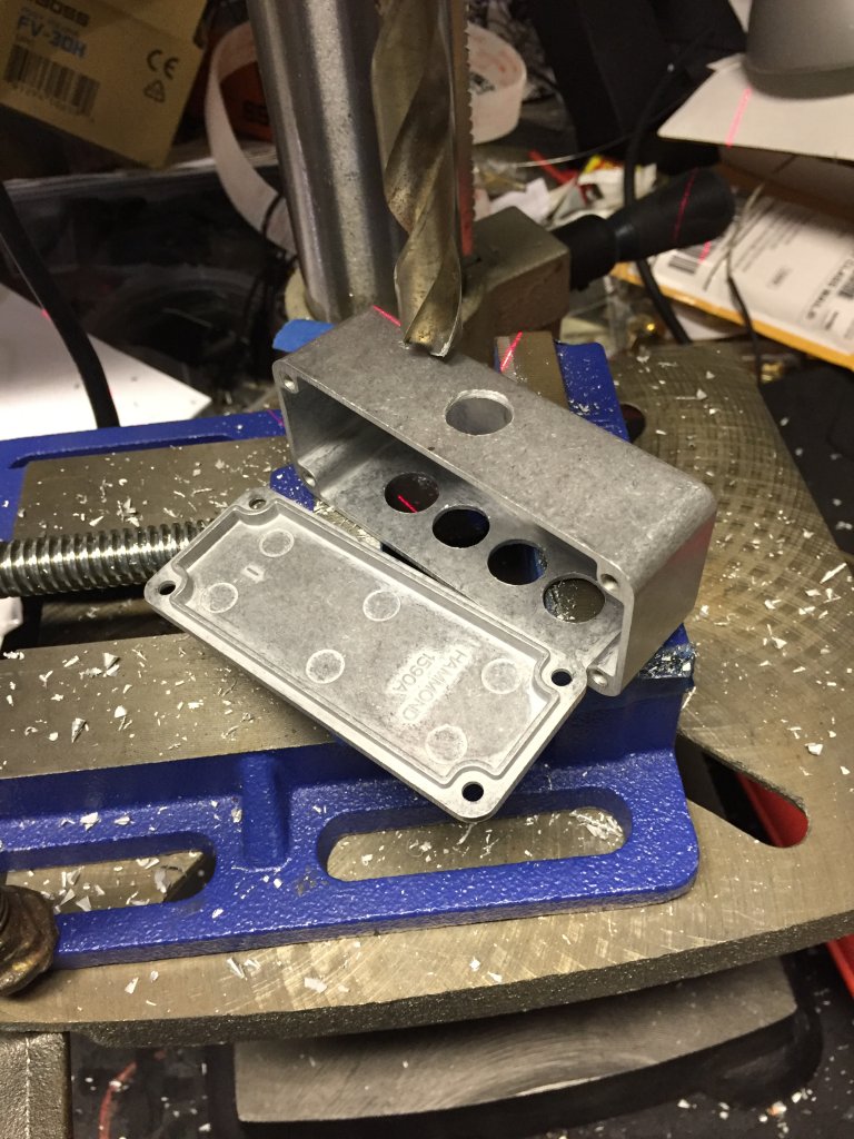
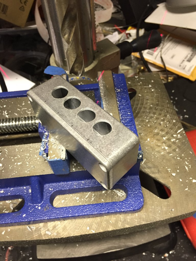
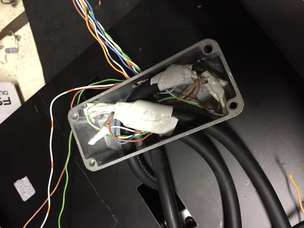
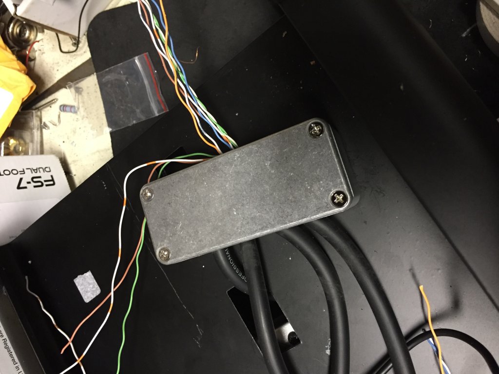
4 for the TRS cables to come in, and one for the CAT5 cables to go out. Inside the box the larger wires are soldered to smaller wires, and then the smaller wires go to the punch-downs on the CAT5e jacks. The A-dapter kit (I’ve since renamed it “The Consolidator Box” since that’s essentially what it does, i.e., consolidate 12 leads down to 9) will be mounted underneath the pedalboard, directly behind the CAT5e jacks.
It would have been nice to make them easy to disconnect, but I need to be concerned about not connecting audio ground to 9VDC ground, and the fact that I’m passing +9VDC through these footswitches, including the sleeves on all 4 TRS cables, well, I don’t want +9VDC to come into contact with audio ground, I suspect things wouldn’t go well if that happened. It wouldn’t be a problem or even a risk if it weren’t for the fact that the volume pedal is also down on that board, plugged in with cables with exposed grounds. And while it won’t likely come into contact with the footswitch cables, it could come into contact with the pedalboard frame, as could the footswitch cables. I think some shrink-wrap insulation is in order. Or at least some electrical tape.
I had some spare time where I was nowhere near the project, so I thought it would be a good idea to put in some thinkin’ time and mentally test my hypotheses as best I could, and perhaps identify and sequence the remaining tasks. I came up with 24 steps (not quite Hitchcock’s 39), and spent part of Sunday (this project has taken so long, I don’t recall WHICH Sunday I’m talking about here) evening working through them.
Upon discovering I was going to need two 9VDC power runs to power both the control box and the SwitchBoard, I needed to find a way to install a second 9V jack in the control box. The good news, there was already a hole in a convenient place where it would fit. The bad news, the diameter of this hole needed to be enlarged. But it’s an aluminum box, and my step drill bit made pretty quick work of it. A little more wiring, a little blowing out of metal fragments created by the drill, and the second jack was installed, the CAT6 jacks rewired, and everything put back together and tested to make sure it all still works. In addition, I completed the footswitch wiring on the pedalboard, which included reducing the TRS cable leads to a size that would punch down on the dual CAT5E jacks, hiding that mess inside a little Hammond box, modifying that duplex CAT5E box with a 9V power outlet jack to plug the footswitches into, and mounting the Hammond box and duplex jack on the bottom of the pedalboard. Tested all of that too (successfully).
Now (then) came the part I’d been putting off until I was sure it was going to work: drilling holes in the toolbox. I haven’t counted exactly how many holes I’m going to have to drill in this poor box, but when I’m done, it’s not going to be much good as an actual toolbox. So far, I’ve put 12 holes in it. 3 for the CAT 5E passthrough connectors, 6 for the screws that hold them in, and 3 to make the I/O box accessible. And I’m just getting started.
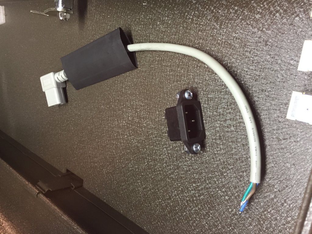
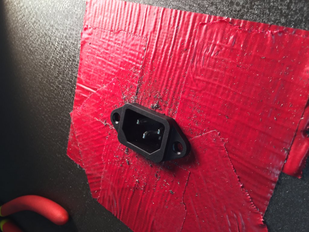
The next hole will probably have to be both drilled and cut, as it’s a 5-sided polygon, the shape of an IEC connector (because it’s an IEC connector) to provide power to the Mondo. And it will really be 3 holes, because I’ll need two additional holes for the mounting screws that will attach to the outside of the tool box to hold it in. But the big hol-ey opportunity will be putting holes in the top tray to run power and audio cables through, and putting them in the backs of the 3 drawers to run power and audio cables through. And I couldn’t do this until I was sure I was going to be able to use the toolbox, and a functioning control box/pedalboard was necessary before green-lighting the drillage of a whole bunch of additional holes, thereby making an $80 toolbox unreturnable.
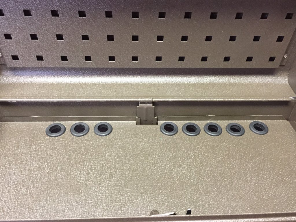
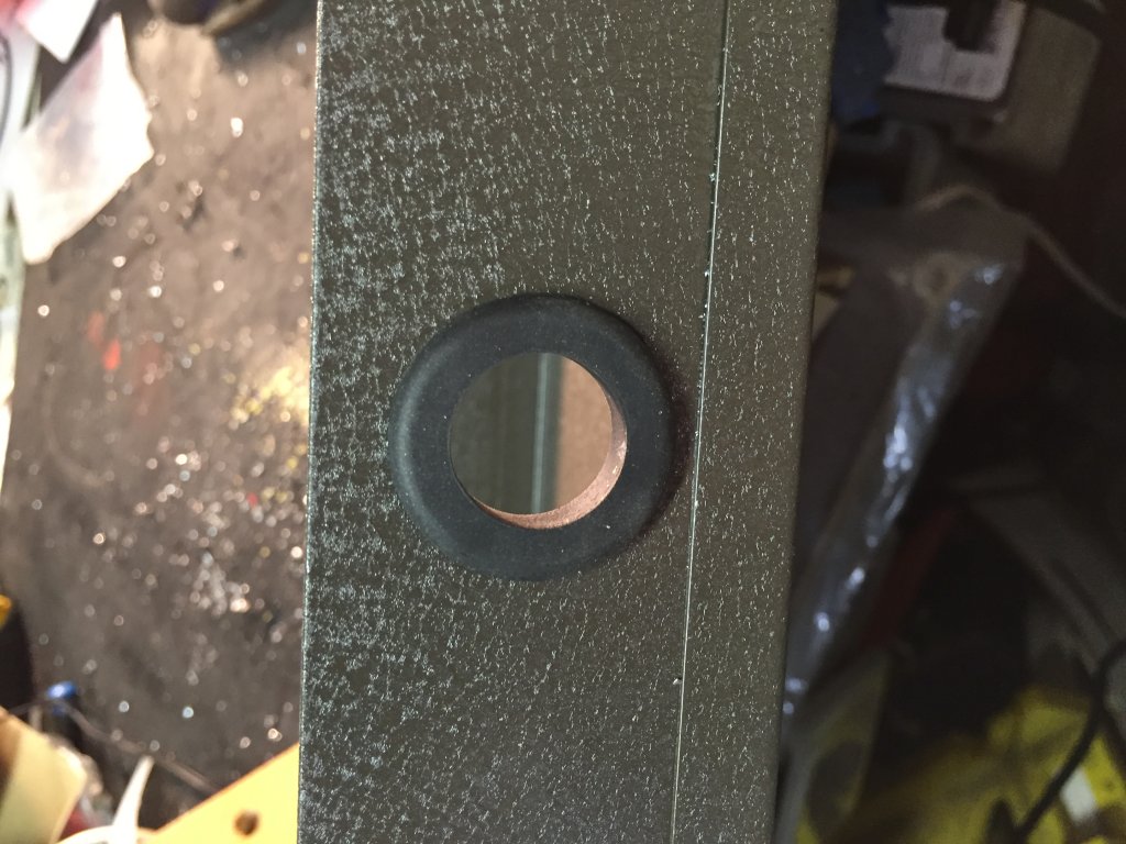
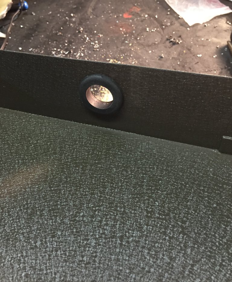
And because these wires will be carrying either DC current or an AC audio signal, and neither of them would benefit from a short-circuit, I need to put grommets in the holes. The biggest grommets I could find at Home Depot were 3/4”, which should work OK, and I thought my 7/8” step drill bit would be fine for that. Then I read the packaging on the grommets and learned that in order to make a 3/4” grommeted hole, the hole in the toolbox was going to need to be 1” in diameter. OK, any excuse to buy new tools. I now have 3 step drill bits, the largest of which goes up to 1-3/8” in diameter. Woo-hoo!
As I think I said (at least once), proof of concept on this project is running about 3 days ahead of execution, so there’s some things I think will work that I haven’t tried yet, and haven’t been in a position to try until a preceding step was validated. So the next hurdle is cable management. For each pedal, a pair of ¼” audio cables will run between the control box in the top tray and the pedal (if I’d been thinking, I could have used insert cables and not needed so many jacks, or cable, but I digress), along with a 9V power cable from the Mondo, which I’m tentatively planning to put in the middle drawer. The trick is, I need to make the cable long enough so the drawer can open and close easily, and the spare cable length needs to reliably either retract or at least store itself in the toolbox where it won’t come disconnected, short out, or block the drawers from opening and closing freely. Which begs the question: “How is that going to work?” And so far, my answer is: “I don’t know.”
There are a variety of approaches I could use. The most common and most popular cables to use for pedalboards is George L’s, and at first it looks very attractive because it’s relatively narrow in diameter and easy to create cables with. But it’s also very stiff and doesn’t necessarily go where you want it to when you push it (or push in the drawers in this case). And it’s also relatively expensive. I could use the skinny generic cable I used inside the control box, but I didn’t feel good about using cheap cable in an application that would have to move around a lot.
So while that was in the ponderment stage, I started measuring how long each patch cable would need to be, and almost all of them came up at or about 2 feet. So I thought “Why not buy some pre-made right-angle, 2-foot patch cables? eBay must have those!” And indeed they do. Even color-coded ones. And they don’t cost much. So I bought 2 bags of 6, each a different color so I’d have color-coded pairs. Or so I thought. As it turned out, a couple weren’t quite long enough, so I had to make a few custom ones with some Mogami cable and Switchcraft 226 plugs I had lying around.
Finally got that done and plugged it in. No smoke, that’s good. All the loops work, let’s go for the gold and actually plug a guitar and an amp into it! Guitar signal in, guitar signal out! Start switching the loops in and out, yup, I can hear that the compressor is doing what it’s supposed to, so’s the boost, the overdrive, the delay, and the EQ. Cool! Tremolo…hmm. Switching it in and out doesn’t seem to make any difference. That’s odd. Listening closely, I can hear the relay pull in and out when I hit the switch. Must be a short inside the box. I had visions of trying to re-solder the little wires I’d used on the perf board, or searching for an errant blob of solder somewhere, it wasn’t going to be fun. So in an effort to avoid that, I looked at other stuff first. When I started running out of space for jacks on the sides of the box, I put a couple on top for loop 6, which was the tremolo loop. I’d had to move one of the power jacks from its original location between the In and Out jacks on the end side, so I use the hole it used to reside in for the loop 6 send (or was it receive?), and a hole on top for the other jack for that loop, leaving one empty hole on top for, er, ventilation, yeah, that’s it.
So I pulled the control box up off its Dual Lock and pulled the cover off. Now I’d only looked at it this way before with nothing plugged into it. This time, though, I had all the plugs in it, and in this situation, I noticed that the contacts for tips of the plugs in loop 6’s send and receive jacks…were touching. So the relay worked, but its effect was negated by the short. All I had to do was rotate one of the jacks a little and that problem was solved. But now instead of no tremolo, I got a big nasty hum whenever I invoked the loop 6. Cable? Yup. One of my bargain 2-footers went bad. Luckily I had a spare, but so much for color coordination. With an 8.3% failure rate on installation, I suspect there will be more Mogami and less color here as time goes on.
Another accomplishment, another challenge. Finally got all the audio cables made and installed. Got all the power cables installed and labeled. Got the IEC inlet installed. Plugged in the power and everything lights up. Tried to close the drawers and the middle one won't go all the way in. Sigh. Lots of cables back there, so they'll need a bit of rearrangement. I pushed the cables into the most out-of-the-way positions I could and discovered that opening and closing the drawers a few times caused most of the cables to follow the path of least resistance and gradually settle out of the way. The middle drawer still puts up a little struggle, so I think I’m going to have to pull it out and cut a bigger accommodation for the IEC inlet. Don’t want the repeated openings and closings of that drawer to eventually wear the insulation off the inlet’s lugs. That would make things a little smoky, then non-functional.
But for now, it works! Going to be a little while before I brave a gig, or even a rehearsal with it, though. I still need to armor the CAT6 and volume pedal cables for stage durability, I just ordered a PedalPython kit to aggregate them into one black snake that will stand up to the abuse it’s likely to receive. Oh, and I haven’t glued the little rubber corners that came with the toolbox on the bottom to keep it from unduly scratching things up or getting scratched. And I’m researching the feasibility of converting it to wireless switching. Gonna be a while on that one.
Here are some other pictures from the project that I either forgot to write about or didn't add much value to the narrative:


I've been working on a few updates and upgrades to the Rackabilly system, which I'll describe/document here.
A few months ago, the good folks at Quilter asked me to beta-test a new amp for them. I had seen a mock-up of it at the NAMM Show in January and was excited when they had working beta units shortly thereafter. It's called the InterBlock and is a full-featured amplifier head slightly bigger than my biggest pedal. Naturally, I felt it needed to be incorporated into the Rackabilly.
Mounting this where I did meant I needed to cable it to provide power from its external power supply, provide easy-access jacks for the speaker(s) and DI, and wire the input so it could be fairly painlessly integrated into the existing input circuit, or bypassed if I chose to use a separate amplifier. More Hammond boxes, cable, zip ties, and shoehorning were required.

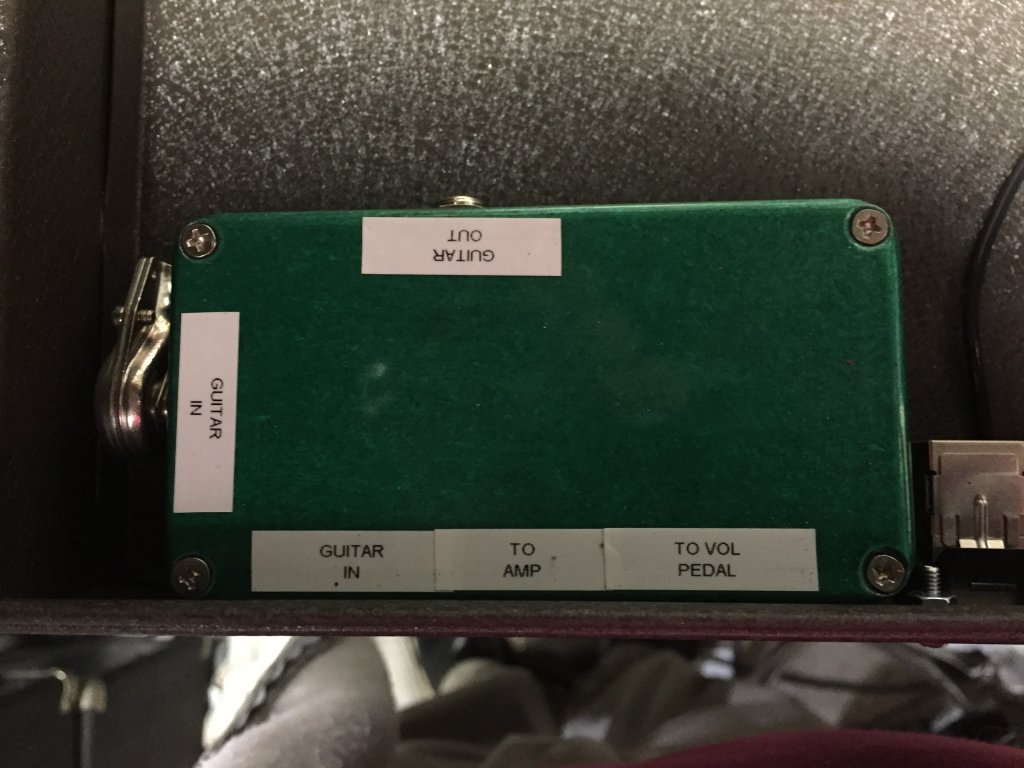
The small green box on the left got a new jack that uses a switching jack. Whenever something's plugged into it, the jack on the side of the toolbox is disconnected and the signal chain routes to whatever's plugged into the switching jack, in this case, the InterBlock. To use an external amp without the InterBlock, I just unplug that inner plug and use the Guitar Out on the side of the toolbox. And this all worked pretty OK until I noticed that even with the InterBlock integrated, I was only using the effects loop for one pedal, and I had to turn it on and off manually (oh, the horror!), and two of the switches on the SwitchBoard weren't doing anything anymore (the two that switched functions on a Quilter amp or any amp with a TRS jack for footswitchable functions). And at the same time, the reverb pedal I'd had in the "always-on" mode didn't get along with the InterBlock unless I powered it with a battery (it gave a lot of obnoxious, noticeable hum). What to do?
It evolved a little as I figured out what I wanted to do. First, I left the reverb pedal where it was and squeezed a Pedtaltrain Volto battery in the drawer next to it. That got rid of the hum and didn't cost anything because I already had the Volto and wasn't using it. I had put the EQ pedal in the lid next to the InterBlock in the effects loop. But it wasn't remotely switchable. Gotta fix that. Whaddya know, I've got two now-unused footswitches on the SwitchBoard, just gotta make it work. How about an add-on loop switcher, one which sits in the amp's effects loop, and since there are two footswitches, why not two switchable loops? In the effects loop. So the Loop the Loop box was born. To make it reversible, I put a CAT5 jack in the Loop the Loop pedal and moved the cable from going to the pass-through jack on the side of the toolbox and into the LtL. That way, if I ever want to remotely control a Quilter amp again, I just move the CAT5 cable back to the pass-through jack on the side of the toolbox and out to the amp with another CAT5 cable. The Loop the Loop (LtL) box is the same circuit as the Big Green Relay Box (BGRB), but with only 2 loops, and learning from previous efforts, I used TRS jacks and homemade insert cables this time to simplify the wiring process. I used Tip for Send, Ring for Return, and didn't look up anything to see if there's any kind of standard for that. I labeled the cable ends Send and Receive so I know what to plug into what at the pedal end.
I found enough "footprint" room for the InterBlock and LtL in the lid of the toolbox, but there wasn't quite enough depth in the lid to accommodate the LtL and still be able to close the lid. But there was a possibility. The toolbox lid has a standoff-type plate, presumably for reinforcement, which is attached to the lid. If I cut out a portion of it, it would buy me enough depth to mount the amp. So bring on the Dremel and the metal cutting wheel.

Cutting took a while.

But eventually, it was done.

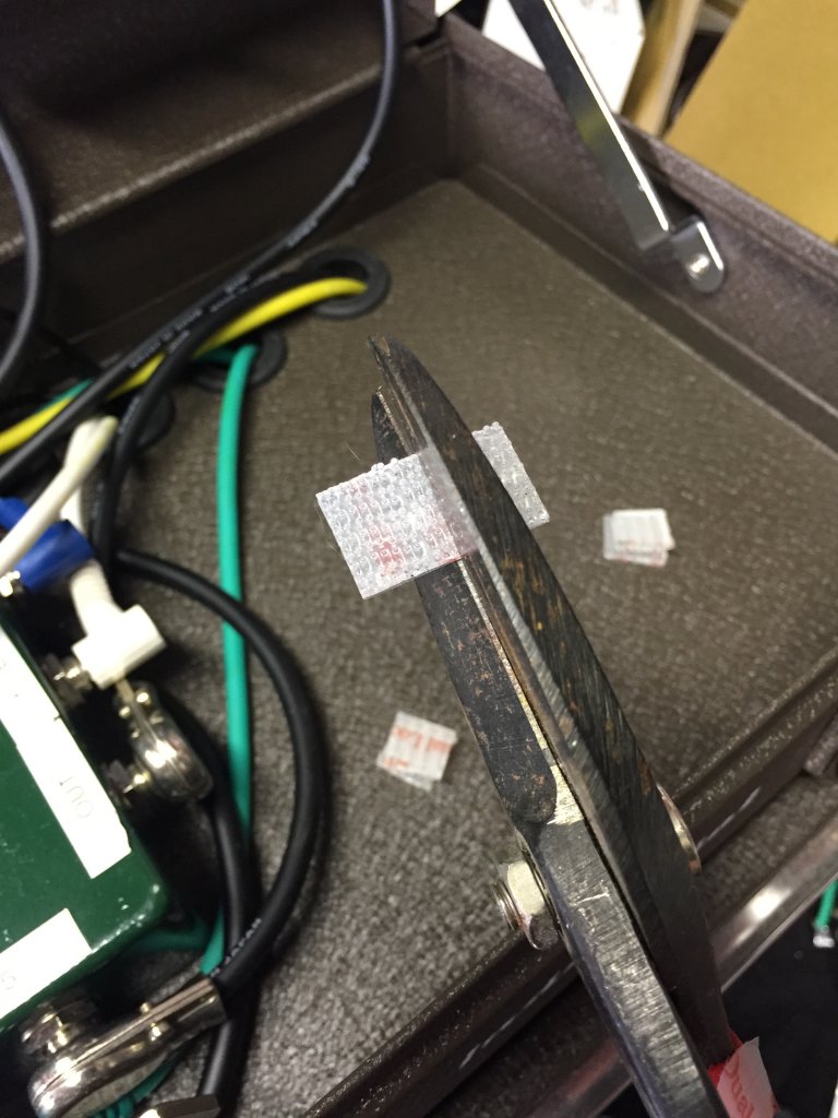
I burned up my old Dremel in the process of cutting this out and had to buy a new one with a little more horsepower. And yes, I smoothed out the edges and covered them with trim tape to not scratch things that get stuck in the hole. And finally, it was done:

And it even works.

I put the EQ pedal and the reverb pedal in the LtL loops, and it didn't take too long for me to forget to turn off the Volto pedal and run it down, thereby turning that loop into an elaborate mute switched if I switched it on, to make me tire of depending upon a battery-operated pedal in this sophisticated, er, complex thing I've created. And I wanted a phase shifter, in case I need to play any Waylon songs. So I thought about it some more and concluded, why don't I feed the InterBlock's DI into an amp with reverb, like a Quilter Pro Block, and then I can get all the clean headroom I could ever want (and I like a lot of clean headroom), and reverb (my reverb needs are simple, I don't need the fancy reverb pedal(s) I have, just a little natural-sounding reverb). Then I could use the extra loop in the LtL for a phase shifter. (You've heard this before): Crazy? Yes, but it just...might...work! And with a lot of purchasing, drilling and soldering, it did. Except when I went to shop for a phase shifter, I fell in love with a UniVibe instead so that's what's in there now. I found a used Pro Block on reverb.com and made an offer, which the seller accepted. I still need to dress all these cables, and now that the Rackabilly is close to two years old, some of the cheap patch cables I bought (the color-coded ones) are starting to wear out and are asking to be replaced. So I envision a weekend of more cutting, stripping, and soldering real soon. But for now, it works. And, side benefit: it gets face-meltingly loud.
That was what I referred to as "Rev. 2" of the Rackabilly. Of course there had to be a Rev. 3. My friend Mel Waldorf (if you haven't seen his Alameda pickups, you need to) showed me a fun little mod to power his Line 6 G10 wireless guitar system. The G10 uses a USB cable to power its receiver/dock, and that doesn't work so well with even the most full-featured pedalboard power supplies. He took one of those automotive (they used to be called "cigarette lighters" back when cars had cigarette lighters) plug-in USB chargers and modded it so he could plug it into one of the 9V ports in his pedalboard power supply, and had a reliable way to power his G10 without a separate power supply. "Cool," I thought. "I'm gonna do that, too." So while in CVS trying (in vain) to get a flu shot, I spotted one of those chargers in the impulse section ("impulse power?" Nah, gonna let that go) near the checkout counter and bought it.

Took it home and did the necessary bastardization as Mel described to make it plug into one of the unused 12V ports on the Mondo.


Then ran a spare USB Micro cable through the Rackabilly from the middle drawer to up top where the G10 dock would sit on the I/O jack box, and it seemed like I was ready to go. It was at that point that I noticed the Mondo's ports are rated at 400ma, and the charger wants a whole ampere, as does the G10 dock. Hmmm, that seems to be asking for trouble. But let's try it, and yes, the USB port lit up, but the G10, not so much. It lit up, flickered, lit up again, and seemed to be starving for current, so I disconnected it.
Now what? I've got the cabling for the G10 in, but gotta find another way to get power to it, ideally from the power supply drawer. I'm already using the convenience outlet on the Mondo to power the Quilter power supply, can I find a two-outlet splitter with a right-angle plug that I can use, and a 1-amp USB power supply? Well of course I can, that's what Amazon is for.

A couple days later I had the splitter (I bought two because I thought it might come in handly, like when I have to plug in the Rackabilly AND the Pro Block and there's only one outlet), and while it's not terribly neat, it's secured in the power supply drawer and doing what it needs to do:


And yes, I've now found a way to make this thing a little heavier. Not sure there's gonna be a Rev. 4, I don't know where else I can put anything in here. But I've already discovered another useful feature: that plug-in USB charger has two ports, so I can charge my phone (or the Volto) while playing a gig. Sucha deal!
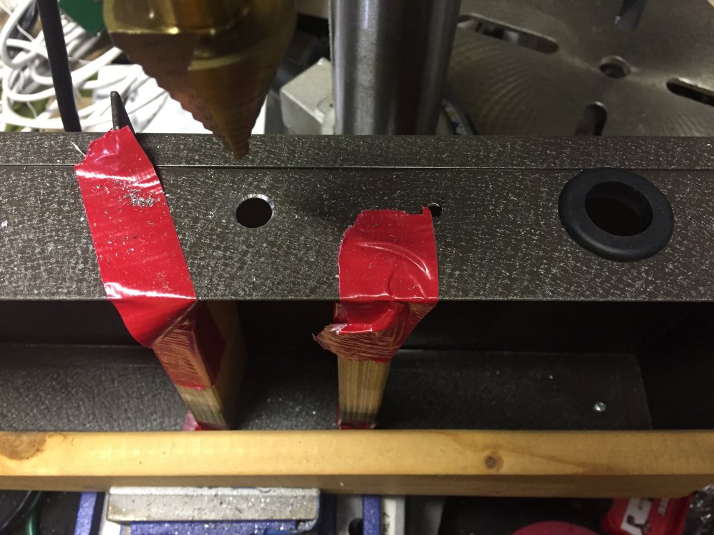
OK, I spoke too soon. In trying to deploy this on stages and other locations, I've faced the problem of "Where do you put it?" The logical place is on top of the amp, and if I'm using the FrontLiner or a 1x15 cab I use when I'm not using the FrontLiner, that's fine, except for the handle on top of either one. I went for the longest time using pieces of wood, held down to the top of the amp or cab with DualLock, and perching the toolbox on top of that. What didn't occur to me until I was practicing one day and looked over at a speaker cabinet I had leaning on its side was: Why not put amp feet on the bottom? Drill 4 holes, screw 'em in, and you're done! I don't know why that didn't occur to me before.
So I looked at the bottom of the toolbox, and whaddya know, there were already 4 holes in it ready to mount rubber feet. Sheesh. $5 later I had 2 sets of 4 rubber amp feet with embedded washers to facilitate mounting, di-rect from Amazon. Bought some stainless pan-head machine screws and nylon-collar nuts at Home Depot, and put 'em in. The hardest part was unplugging the four pedals in the bottom drawer, keeping track of the cables, and reinstalling them afterward. So now the Rackabilly sits about 3/4" higher, and will clear most any amp handle it has to straddle.
How hard can this be?

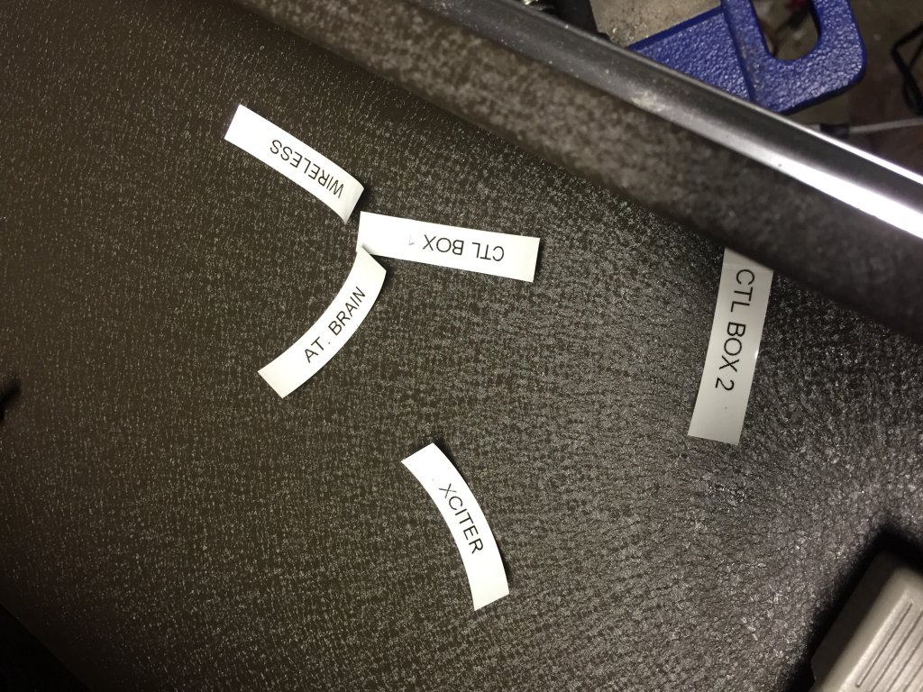
First things first, let's keep track of the cabling:
![]()
Bolted down nice and tight. The screws could have been 1/4" shorter, but they're well clear of the bottom of the bottom drawer:

Nice and tight on the outside, too:

All done:

Maybe a little hillbilly branding, thanks to Dymo:

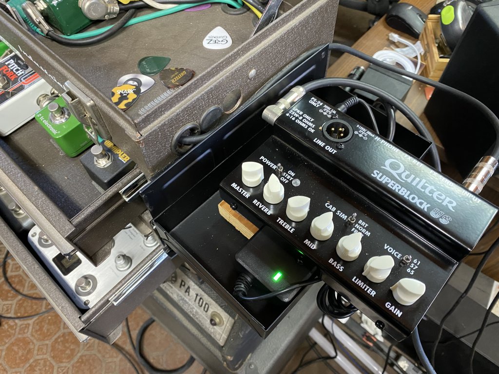
June 24, 2021 – A New Amp for the Rackabilly
I bought a little
Quilter Superblock, and while it’s small, it’s still too big to shoehorn into
any of the available space left in the toolbox.
So I thought about hanging it on the side of the box, which seemed like
sort of a good idea, but how to make a shelf to do that with? Fabricating one seemed like a lot of work,
and high school metal shop was a long time ago, so I started seeking out
options, and whaddya know, toolbox makers make
magnetic shelves that stick on the sides of toolboxes to hold tools, parts,
etc. Well that sounds perfect, if I can
find one the right size. After some
searching, I concluded I wasn’t going to find the exact right one, but maybe,
just maybe, I could improvise with one that comes close. And I found one, it would actually be pretty
much perfect if I mounted the amp perpendicular, but dyslexia aside, I still
didn’t want to read the knob labels sideways, so I opted to cantilever the amp
over the side of the tray. Only trouble
was, the tray is more of a drawer, so its bottom is about an inch below the top
edge. As luck would have it, though, the
power brick for the Quilter SuperBlock is about
exactly the same thickness as the depth of the drawer, so it becomes a perfect
perch on which to mount the amp. I used
a wood block I already had that had some Dual Lock already on it, added some
more to the bottom of the tray and the underside of the amp, and, like a charm,
the amp mounts fairly securely on the tray, the tray hangs fairly securely on
the toolbox, and once I made an input cable that goes from the toolbox to the
amp input, we’re done!
I bought a piece
of Lexan, which I was going to cut and sit the amp on, but it’s pretty stable
the way it is, and will come apart and pack up pretty easily when the show’s
over, so I’m going to try it this way and see how it goes.